In this article, you’ll learn about two other important AutoCAD features: ORTHO Mode and Polar Tracking.
Let’s begin with the first one:
A. ORTHO Mode
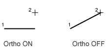
ORTHO (Orthogonal Mode) is used to constrain cursor movement to horizontal or vertical directions while executing commands.
One example of using this feature is when you want to create a perfectly horizontal line. Even if the start and end points are not perfectly aligned, the line will remain perfectly horizontal as long as ORTHO is enabled.
Look at the illustration below:
ORTHO is also very helpful when moving or copying objects, or performing other operations in horizontal or vertical directions.
The ORTHO feature can be turned on or off by clicking the ORTHO button ![]() on the Status Bar or by pressing F8 on the keyboard.
on the Status Bar or by pressing F8 on the keyboard.
B. Polar Tracking
Polar Tracking helps constrain the cursor movement to specified angles while executing commands.
This feature can be turned on or off by clicking the Polar Tracking button ![]() on the Status Bar or by pressing F10 on the keyboard.
on the Status Bar or by pressing F10 on the keyboard.
A Polar Tracking line appears when creating lines, moving objects, rotating objects, and performing several other operations whenever the cursor aligns with a specified polar angle.
You can set the Polar Tracking interval by clicking the dropdown arrow next to the Polar Tracking icon on the Status Bar and selecting the desired interval.
You can also add custom angles that are not included in the available interval list by right-clicking on the Polar Tracking icon in the Status Bar and choosing “Tracking Settings”. Then enter the desired angle in the “Additional Angles” section.
Note: ORTHO and Polar Tracking cannot be enabled at the same time. When you enable the ORTHO feature, the Polar Tracking feature will automatically be disabled, and vice versa.
Leave a Reply