
In this article, you will learn how to use the CHAMFER command in AutoCAD.
The CHAMFER command creates a beveled edge between two objects in 2D drawings or between two adjacent faces on a 3D solid.
Although the CHAMFER command can also be used with 3D objects, this article focuses only on its use in 2D drawings. For 3D solids, it is generally easier to create chamfers using the CHAMFEREDGE command, which will be covered in a separate article.
The icon and keyboard shortcut for the CHAMFER command are shown in the table below.
| Command | CHAMFER |
| Function | Creates a beveled edge between two objects in 2D drawings or between two adjacent faces on a 3D solid. |
| Icon |  |
| Shortcut | CHA |
The CHAMFER command is one of the most commonly used Modify commands. To activate it, click the CHAMFER icon in the Modify panel on the Home tab of the Ribbon.
If the Menu Bar is enabled in your workspace, you can access the CHAMFER command from the Modify menu.
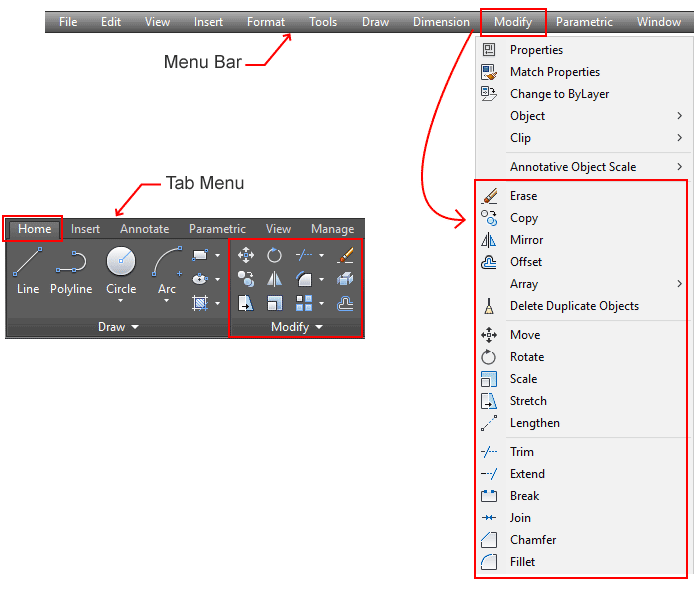
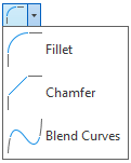
The CHAMFER command is grouped with the FILLET command in the Ribbon. You may need to click the drop-down arrow next to FILLET to access CHAMFER.
If you prefer using the command line, simply type CHA and press Enter to start the CHAMFER command.
A. Chamfer Methods
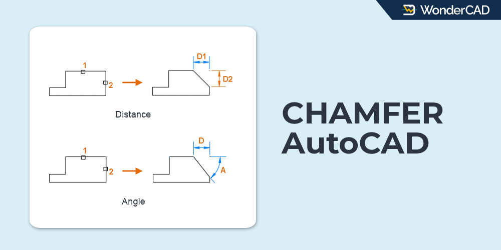
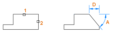
Chamfers can be created using two methods: the Distance method and the Angle method.
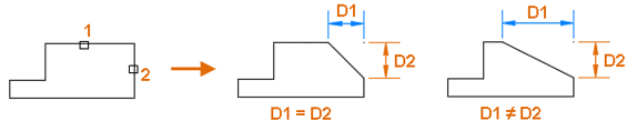
Distance Method: Creates a chamfer by specifying the chamfer distances along the first and second lines. These distances may be equal or different.
Angle Method: Creates a chamfer by specifying a chamfer distance along the first line and a chamfer angle measured from the first line.
B. How to Create a Chamfer in AutoCAD
This section explains the step-by-step process for creating chamfers using both the Distance and Angle methods.
To create a chamfer using the Distance method, follow the steps below:
- Activate the CHAMFER command.
- Select the Distance option from the command line.

- Enter the chamfer distance for the first line, then press Enter.
- Enter the chamfer distance for the second line, then press Enter.
- Select the first line.
- Select the second line.

To create a chamfer using the Angle method, follow the steps below:
- Activate the CHAMFER command.
- Select the Angle option from the command line.
- Enter the chamfer distance for the first line, then press Enter.
- Enter the chamfer angle for the first line, then press Enter.
- Select the first line.
- Select the second line.

If you’re not familiar with selecting command-line options, read our complete tutorial here.
C. Prompts and Options
When running the CHAMFER command, you may see the following prompts and options:
- Select first line: You are prompted to select the first line to be chamfered.
- Select second line or Shift-select to apply corner: You are prompted to select the second line to be chamfered.
Alternatively, hold “Shift” while selecting the second line to create a sharp corner instead of a chamfer. - Undo: Cancels the last chamfer operation.
- Polyline: Applies the same chamfer to all corners of a polyline at once.
- Distance: Sets the chamfer distances for the first and second lines.
- Angle: Sets the chamfer distance for the first line and the chamfer angle measured from that line.
- Trim: Controls whether the original corner is trimmed after the chamfer is created.
- Trim: The original corner is trimmed.
- No Trim: The original corner is kept.
- Multiple: Allows you to create chamfers on multiple corners without restarting the command.
Leave a Reply