When creating a drawing in AutoCAD, you will need to define many points, such as start points, end points, center points, and more. To determine these points efficiently and accurately, you need to understand AutoCAD coordinate systems and the methods used to specify point locations.
Let’s begin with coordinate systems.
A. Coordinate Systems
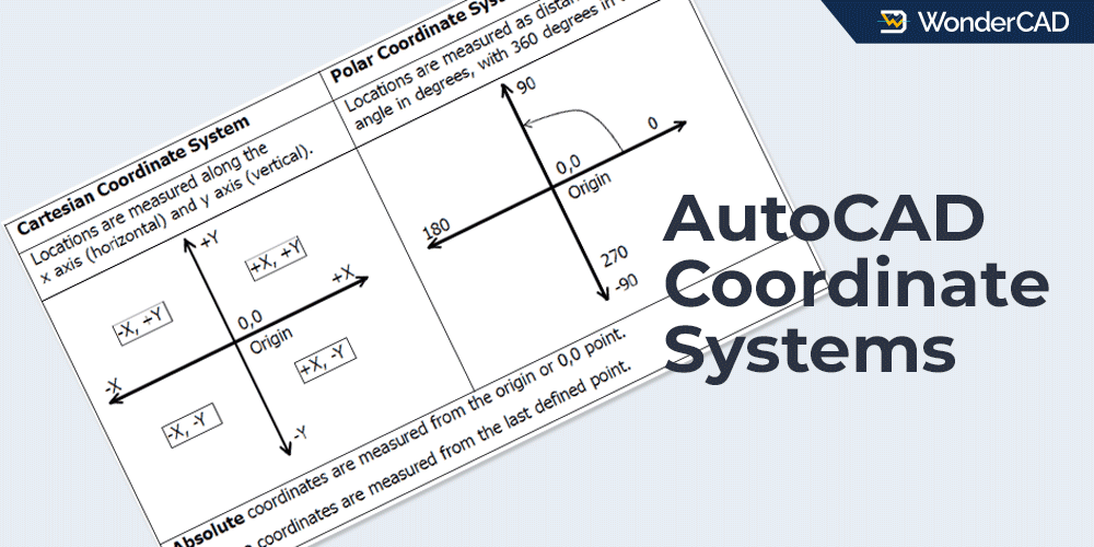
In AutoCAD, you can determine point locations using two coordinate systems: the Cartesian Coordinate System and the Polar Coordinate System.
In the Cartesian Coordinate System, a point location is determined by its X and Y coordinate values. The X-axis represents horizontal movement, while the Y-axis represents vertical movement.
The Polar Coordinate System uses distance and angle values to determine a point location.
The coordinate system you use depends on the information available. If you know the X and Y coordinates of a point, use Cartesian coordinates. However, if you know the exact angle between two points and their distance, use Polar coordinates.
For more details, see the image below:
B. Methods for Determining Point Location
There are six methods for specifying point locations in AutoCAD. Below is an explanation of each method.
1. Interactive Method
This method determines a point by clicking directly in the drawing area. This method is the least accurate unless you enable OSNAP.
2. Absolute Cartesian Coordinate Method
This method determines a point location by typing X and Y coordinate values into the command line. All coordinate values in this method are relative to the origin (0,0).
The format for entering Absolute Cartesian coordinates is: x,y
- x : coordinate value for X axis
- y : coordinate value for Y axis.
- The x and y values are separated using a comma (,) without spaces.
3. Relative Cartesian Coordinate Method
This method determines a point location by typing X and Y coordinate values into the command line. However, all coordinate values in this method are relative to the previous point in the same command.
Because the coordinates are measured from the previous point, this method cannot be used to specify the first point.
The format for entering Relative Cartesian coordinates is: @x,y
4. Relative Polar Coordinate Method
This method determines a point location based on a distance and angle measured from the previous point. Like the Relative Cartesian Method, this method cannot be used to specify the first point.
The format for entering Relative Polar coordinates is: @distance<angle
- Distance: The distance from the previous point.
- Angle: The direction of the new point relative to the previous point.
5. Direct Distance Entry Method
This method allows you to specify a point by entering a distance measured from the previous point.
To use it, move the cursor away from the previous point in the desired direction, then type the desired distance and press Enter. For accurate results, use ORTHO or Polar Tracking.
6. Surveyor’s Coordinates
This method is similar to Relative Polar Coordinates, but uses a different notation. It is commonly used in surveying and land mapping.
An example of writing coordinates using this method is @100<n30d45’e. This means the direct distance from the previous point is 100 units and the direction is North 30°45′ East.
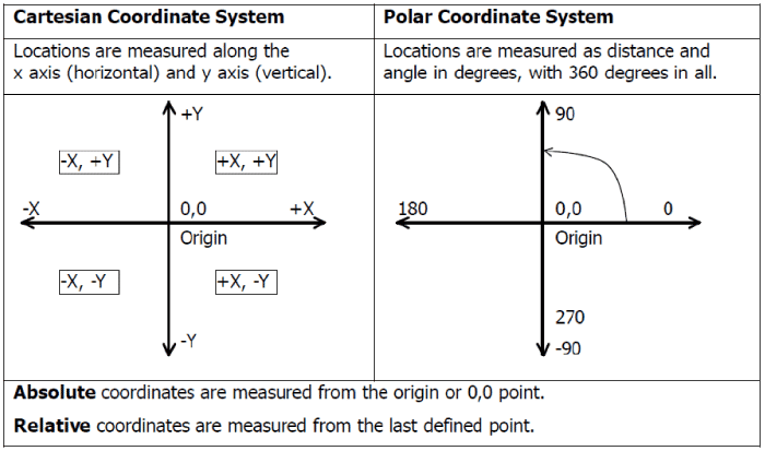
C. Example
In this section, you will learn how to determine point locations using various methods.
See the illustration below:
1. To Point B from Point A:
- Absolute Cartesian coordinates: 0,0 (A) and 4,4 (B)
- Relative Cartesian coordinates for Point B: 0,0 (A) and @4,4 (B)
- The Interactive Method can be used by clicking directly on the drawing area when the Grid Snap feature is active with Snap Distance set to 1, 2 or 4.
2. To Point D from Point C:
- Absolute Cartesian coordinates: -3,0 (C) and -3,4 (D)
- Relative Cartesian coordinates for Point D: -3,0 (C) and @0,4 (D)
- Relative Polar Coordinates for Point D: -3,0 (C) and @4<90 (D)
- Direct Distance Entry for Point D: -3,0 (C) and 4 (D) with ORTHO enabled and cursor above Point C
- The Interactive Method can be used by clicking directly on the drawing area when the Grid Snap feature is active with Snap Distance set to 1, 2 or 4.
3. To Point F from Point E:
- Absolute Cartesian coordinates: -3,-4 (E) and 3,-2 (F)
- Relative Cartesian coordinates for Point F: -3,-4 (E) and @6,2 (F)
- The Interactive Method can be used by clicking directly on the drawing area when the Grid Snap feature is active with Snap Distance set to 1 or 2.
Note: From point A to point B and from point E to point F, the Relative Polar Coordinate Method cannot be used because the direct distance between two points is unknown. Of course, you can calculate it first, but that would be inefficient.
Leave a Reply