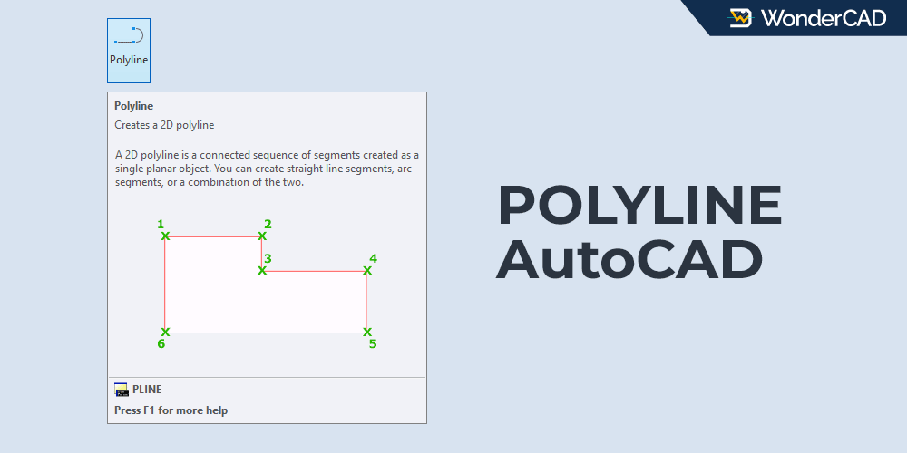
The POLYLINE command in AutoCAD allows you to create a single object made up of connected straight line segments and, optionally, arc segments. You can also create a single object consisting of multiple segments with different widths.
If the last segment is connected to the first segment to form a closed shape, the polyline can later be extruded into a 3D solid object.
This command is included in the DRAW command group.
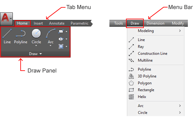
You can activate the POLYLINE command from the Ribbon Panel by clicking its icon in the Draw panel under the Home tab.
You can also activate the POLYLINE command from the Draw menu on the Menu Bar.
If you prefer using the command line, type POLYLINE or simply type PL and then press Enter.
| Command | POLYLINE |
| Function | Create a single object consisting of connected straight line segments and optional arc segments |
| Icon | |
| Shortcut | PL |
A. How to use the POLYLINE command
If you want to create a polyline consisting only of connected straight line segments, the process is exactly the same as when using the LINE command.
However, if you want to create a polyline that contains both line segments and arc segments, follow the steps below:
- Activate the POLYLINE command.
- Specify the starting point of the polyline.
- Specify the next points (second, third, and so on) to create straight line segments.
- Select the Arc option from the command line to create an arc segment that is tangent to the previous segment.
- Select the Line option from the command line to continue creating straight line segments.
- Press Enter to finish the command.
Click here for a complete explanation of how to activate commands in AutoCAD and select options from the command line.
B. Prompts and Options
When running the POLYLINE command, several prompts and options may appear on the command line, including:
- Specify start point: Specify the starting point of the polyline.
- Specify next point: Specify the next point. This point will connect to the previous point to create a straight line segment.
If you want to create an arc segment instead, select the Arc option from the command line. - Arc: Use this option to create an arc segment that is tangent to the previous segment.
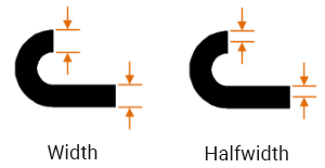
- Halfwidth: Use this option to specify the distance from the center of a wide segment to one of its edges.
- Width: Use this option to specify the width of the next segment.

- Length: Use this option to create a segment with a specified length at the same angle as the previous segment. If the previous segment is an arc, the new line segment will be tangent to that arc.
- Undo: Removes the most recently added segment.
If you select the Arc option, the following options will appear on the command line:
- Angle: Use this option to specify the included angle of the arc segment from the start point.

- Radius: Use this option to specify the radius of the arc segment.
- cEnter: Use this option to specify the center point of the arc.
- Second Pt: Use this option to specify a second point on the arc.
- Line: Use this option to return to creating straight line segments.
Click here for a detailed explanation of how to specify point locations and coordinates in AutoCAD.
C. Example
Below is an example of creating an object using the POLYLINE command. We will start from point A.
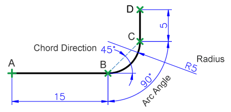
Note: In the image above, the polyline is represented by the black line. Don’t forget to enable ORTHO mode to ensure the horizontal and vertical segments are accurate.
To create a polyline object like the one shown above, follow these steps:
- Activate the POLYLINE command.
- Specify the starting point of the polyline.
- Move the cursor to the right, type 15, and then press Enter.
- Select the Arc option from the command line.
- Select the Radius option, type 5, and then press Enter.
- Select the Angle option, type 90, and then press Enter.
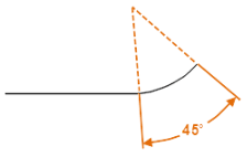
- When the prompt “Specify direction of chord for arc” appears, type 45 and then press Enter.
- Select the Line option from the command line.
- Move the cursor upward from the last point, type 5, and then press Enter.
- Press Enter again to end the command.
If you have difficulty creating arc segments with the POLYLINE command, you can create the polyline using only straight segments first and then use the FILLET command to create the arcs.
Leave a Reply