This article explains the names of the parts of the AutoCAD user interface and their functions. This is very important to understand for people who are going to learn AutoCAD.
Why is that?
Because when we learn AutoCAD through articles or YouTube videos, a tutor often mentions the name of parts from the user interface.
For example, the sentence “you can activate commands from the command line“. A beginner who doesn’t know what a command line is will certainly be confused.
Therefore, let’s learn the names and functions of the different parts of the AutoCAD user interface.
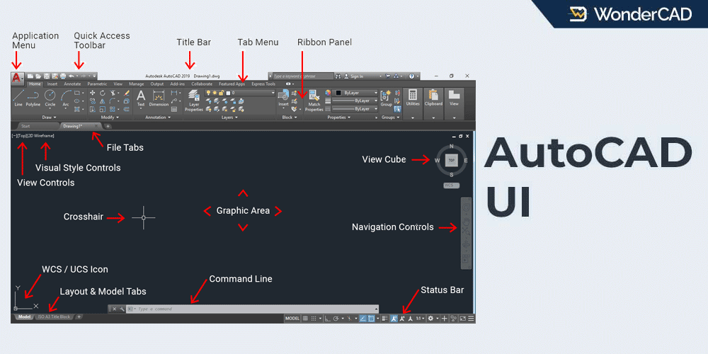
Look at the picture below:
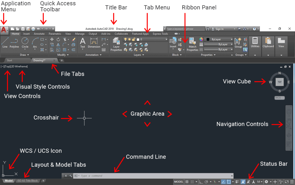
The image above has already told us about the name of parts from AutoCAD user interface and their locations.
Now I will explain the function of each part of the user interface indicated in the image above.
1. Application Menu
The Application Menu is the AutoCAD logo button located in the upper left corner of the screen.
If we click it, the Application Menu contains standard menus that are common in other applications such as New, Open, Save, Save As, etc.
2. Quick Access Toolbar
The Quick Access Toolbar contains commands that we often use. By default, this section contains the New, Open, Save, Save As, Undo and Redo commands.
These commands are also in the Application Menu, but in this position, the commands become directly visible and easier to reach.
We can add or reduce commands in it by right-clicking on the Quick Access Toolbar area, then selecting Customize.
3. Title Bar
The Title Bar is located at the top of the middle screen. This section contains information about the AutoCAD version and is followed by the file name or title of the currently opened document.
Example: “Autodesk AutoCAD 2017 Turbin-Design.dwg”
4. Tabs Menu / Ribbon Tabs
The Tabs Menu, also known as Ribbon Tabs, is located directly below the Title Bar. These tabs serve as selectors for choosing which set of panels will be displayed in the Ribbon.
5. Ribbon Panel
The Ribbon Panel is located right below the Tab Menu. It contains commands organized into different categories.
6. File Tabs
When multiple drawings are open, File Tabs allow users to quickly switch between drawings. Simply click the tab corresponding to the drawing title you want to open.
7. View Controls
View Controls are used to adjust the viewing direction of the drawing, such as Front, Right, Top, and other standard views.
8. Visual Style Control
Visual Style Controls are used to adjust the visual appearance of a model, such as Wireframe, Conceptual, Realistic, and other display styles. This feature is especially useful when creating and reviewing 3D designs.
9. Crosshair
The Crosshair replaces the standard mouse cursor within the AutoCAD drawing area.
The cross-shaped cursor (+) is called the Crosshair, while the small square at its center is known as the Pickbox.
10. Graphic Area
The Graphic Area is the largest part of the interface. It is the area where you create and work on your drawings.
11. View Cube
The View Cube serves the same purpose as View Controls, but it provides a more interactive way to change the viewing orientation.
If you prefer using View Controls, you can hide the View Cube by clicking the minus [-] symbol next to View Controls and then clearing the check mark from the View Cube option. Hiding the View Cube gives you a larger Graphic Area to work with.
12. WCS / UCS Icon
The WCS / UCS Icon indicates the direction of the X, Y, and Z axes.
WCS (World Coordinate System) is the name given to AutoCAD’s default coordinate system. In contrast, UCS (User Coordinate System) is a coordinate system that has been moved or adjusted to suit the user’s needs.
The orientation of the WCS / UCS axes will affect several AutoCAD commands such as EXTRUDE, ARRAY, etc.
13. Model & Layout Tab
The Model Tab and Layout Tab is a selector under the workspace, it used to switch between Model Space and Layout Space.
Model space contains the workspace where the design is made and Layout space contains paper space to prepare the design for printing.
14. Command Line
The Command Line is a long panel located below the drawing area.
It allows users to enter commands directly and provides guidance for the currently active command.
15. Status Bar
The Status Bar is located at the bottom of the AutoCAD window.
The Status Bar contains status information for several features in the active drawing, such as ORTHO, OSNAP, POLAR Tracking, etc.
16. Menu Bar & Tool Bar
If you are using the AutoCAD Classic workspace, the Tab Menu and Ribbon Panel will no longer be displayed. Instead, you will see the Menu Bar and Toolbars, as shown in the figure below.
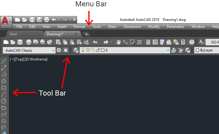
The Menu Bar is a row of menus located directly below the Title Bar.
The Menu Bar contains a row of AutoCAD menus such as File, Edit, View, Insert, Tools, Draw, Modify, etc. These menus contain commands that have been grouped according to their function.
A Toolbar is a panel that contains AutoCAD tools grouped according to their functions. By default, the Draw toolbar is located on the left side of the screen, while the Modify toolbar is displayed on the right side. Other toolbars, such as the Layer toolbar, are typically located at the top of the screen. However, you can arrange the toolbars to suit your preferences by simply dragging and dropping them wherever you want on the screen.
Leave a Reply