In this tutorial, you will learn how to use the ARC command in AutoCAD.
The ARC command is used to create arcs in AutoCAD. The icon and keyboard shortcut for the ARC command are shown in the table below.
| Command | ARC |
| Function | Create an arc |
| Icon | |
| Shortcut | A |
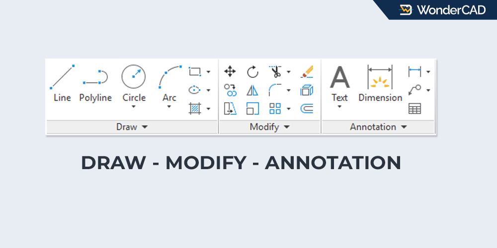
The ARC command belongs to the DRAW command group.
You can find and activate this command from the Draw panel on the Ribbon under the Home tab. You can also find it in the Draw menu on the Menu Bar.
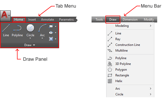
If you prefer using the command line, type ARC or simply type A and then press Enter.
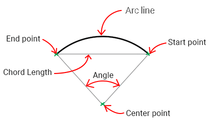
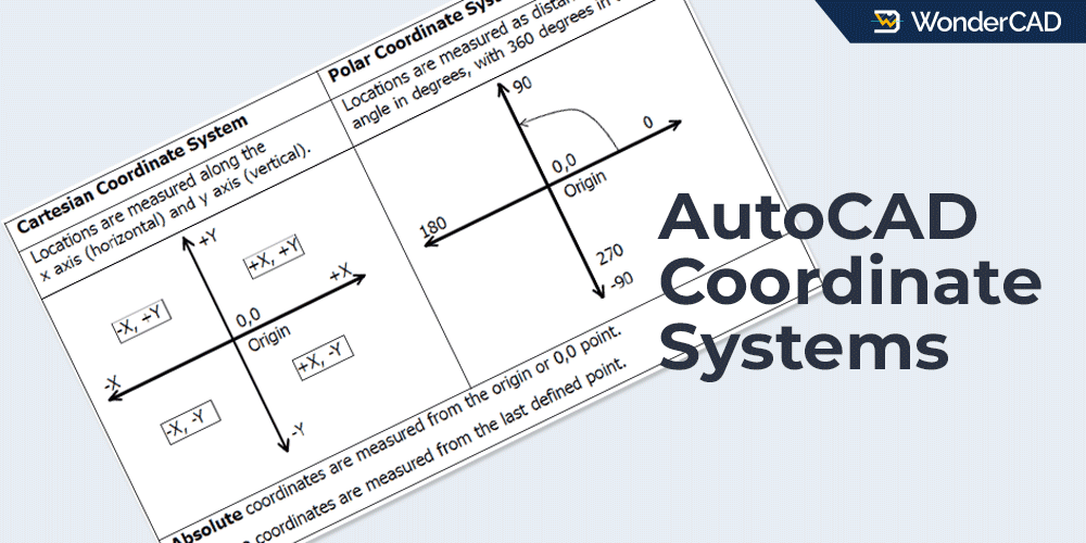
An arc can be defined by several parameters, including the start point, end point, center point, radius, angle, and chord length.
Because of these parameters, AutoCAD provides several different methods for creating arc objects.
To see all available arc creation methods, click the drop-down menu below the Arc icon in the Ribbon. These methods are also available as command line options when the ARC command is active.
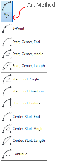
By default, an arc is created by specifying three points: a start point, a second point, and an end point. AutoCAD automatically calculates the center point and radius based on the positions of these three points.
A. How to Create an Arc (Default Method)
To create an arc using the default method, simply follow the steps below:

- Activate the ARC command.
- Specify the start point of the arc.
- Specify the second point.
- Specify the end point.
AutoCAD will create an arc that passes through the three points you selected.
B. Other Arc Creation Methods
If you want to create an arc using a different method, simply choose one of the available options from the Arc method list. Then follow the prompts displayed on the command line.
The name of each method indicates the order of the required inputs. For example, the “Start, End, Angle” method means that you first specify the start point, then the end point, and finally the arc angle.
Some arc creation methods automatically generate arcs in a counterclockwise (CCW) direction.
If you want to reverse the arc direction while creating it, press Ctrl on your keyboard.
C. Command Prompts and Options
When you run the ARC command, several prompts and options may appear on the command line, including:
- Specify start point of arc: Prompts you to specify the starting point of the arc.
- Specify second point of arc: Prompts you to specify the second point used to define the arc.
- Specify end point of arc: Prompts you to specify the ending point of the arc.
- Center: Allows you to specify the center point of the arc.
- End: Allows you to specify the end point of the arc.
- Angle: Allows you to define the included angle of the arc.
- Chord Length: Allows you to specify the chord length, which is the straight-line distance between the start point and end point of the arc.
Leave a Reply