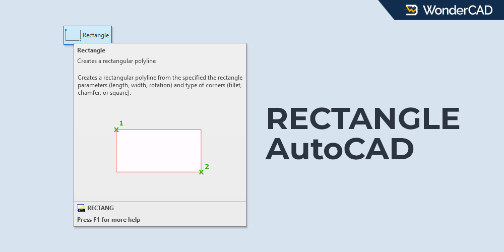
The RECTANGLE (RECTANG) command in AutoCAD is used to create square or rectangular polyline objects instantly.
This command provides several options for creating rectangles by specifying parameters such as dimensions, area, and rotation.
If needed, you can also create rectangles with chamfers or fillets at each corner in a single command session.
| Command | RECTANGLE |
| Function | Create square or rectangular polyline objects instantly |
| Icon | |
| Shortcut | REC |
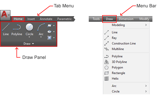
The RECTANGLE command belongs to the DRAW command group.
You can find and activate this command from the Draw panel on the Ribbon under the Home tab. You can also find it in the Draw menu on the Menu Bar.
If you prefer using the command line, type RECTANGLE or simply type REC and then press Enter.
A. How to Use the RECTANGLE Command
You can create many variations of rectangle objects with a single command. However, in this section, I will only show how to create a basic rectangle using the default method.
Examples of creating rectangles by specifying dimensions, area, and corner styles are explained later in the Examples section.
To create a standard rectangle using the default method, follow these steps:
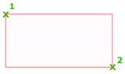
- Activate the RECTANGLE command.
- Specify the first corner point.
- Specify the opposite corner point of the rectangle.
You can specify points using various methods. Read the full explanation here.
B. Prompts and Options
When running the RECTANGLE command, there will be several prompts and options on the command line, including:
- Specify first corner: Specify the first corner point of the rectangle.
- Specify other corner: Specify the opposite corner point of the rectangle. This point and the first corner form a diagonal line.
- Chamfer: Use this option to create chamfers on all corners of the rectangle.
- Elevation: Use this option to specify the elevation of the rectangle along the Z-axis.
- Fillet: Use this option to create fillets on all corners of the rectangle.
- Thickness: Use this option to specify the thickness of the rectangle along the Z-axis.
- Width: Use this option to specify the width of the rectangle polyline (x,y axis).
The following options become available after specifying the first corner:
- Area: Use this option to create a rectangle by specifying its area.
- Dimension: Use this option to create a rectangle by specifying its length and width.
- Rotation: Use this option to create a rectangle by specifying a rotation angle.
C. Examples
In this section, I will show some examples of creating rectangles using commonly used parameters.
» Create a Rectangle by Specifying Its Dimensions
For this example, we will create a rectangle measuring 20 × 10, where 20 is the horizontal length (X-axis) and 10 is the vertical length (Y-axis).
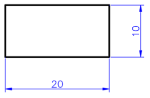
To create the rectangle shown above:
- Activate the RECTANGLE command.
- Specify the first corner point.
- Select the Dimensions option from the command line.
- Specify the rectangle length (X-axis): type 20 and press Enter.
- Specify the rectangle width (Y-axis): type 10 and press Enter.
- Specify the opposite corner point.
» Create a Rectangle by Specifying Its Area
When using the Area option, AutoCAD will ask you to specify either the Length (X-axis) or Width (Y-axis).
In this example, we will create a rectangle with an area of 250 and a length of 17 units along the X-axis.
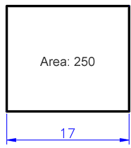
To create the rectangle shown above:
- Activate the RECTANGLE command.
- Specify the first corner point.
- Select the Area option from the command line.
- Type 250 and press Enter.
- Select the Length option.
- Type 17 and press Enter.
- Specify the opposite corner point.
» Create a Rectangle with Fillets
For this example, we will create a rectangle measuring 20 × 10 with R3 fillets at all corners.
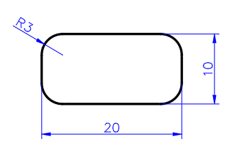
To create the rectangle shown above:
- Activate the RECTANGLE command.
- Select the Fillet option from the command line.
- Specify the fillet radius: type 3 and press Enter.
- Specify the first corner point.
- Select the Dimensions option from the command line.
- Specify the rectangle length (X-axis): type 20 and press Enter.
- Specify the rectangle width (Y-axis): type 10 and press Enter.
- Specify the opposite corner point.

Leave a Reply