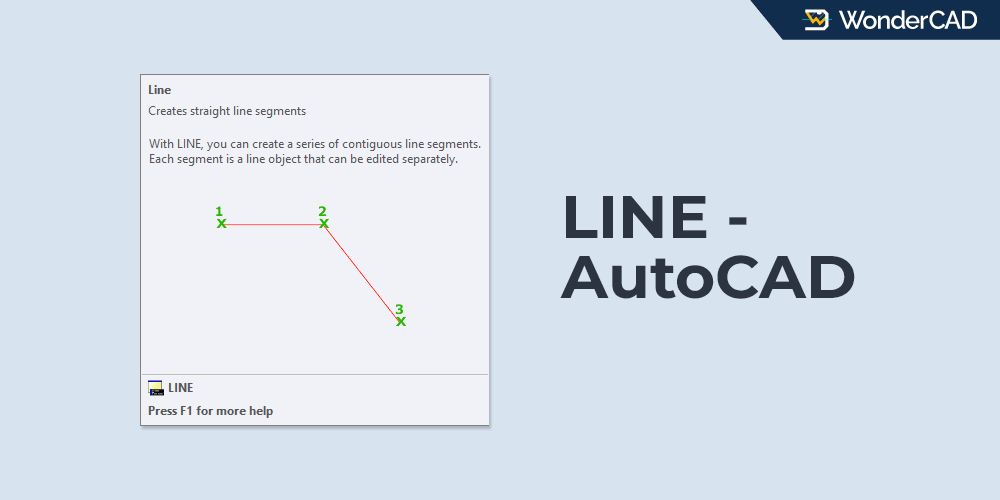
The LINE command is used to create straight line segments. It can be used to draw a single line segment or multiple connected line segments.
The LINE command belongs to the DRAW command group.
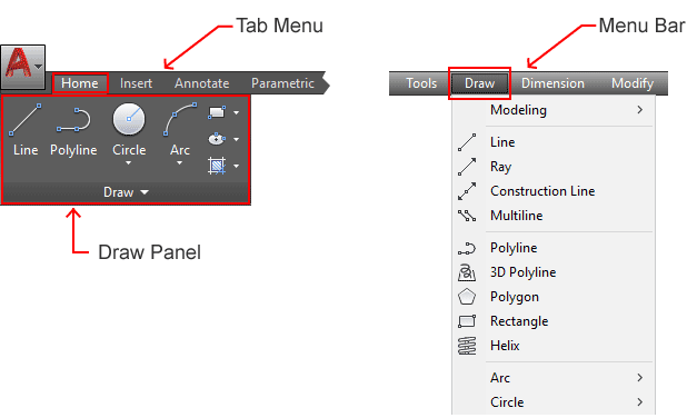
If your workspace includes the Ribbon panel, you can find this command in the Draw panel under the Home tab. Otherwise, you can find it in the Draw menu on the Menu Bar.
You can also activate the LINE command by typing LINE on the command line and pressing Enter, or simply type L and press Enter.
Click here for a complete explanation of how to activate commands in AutoCAD and select options from the command line.
| Command | LINE |
| Function | Create straight line segments |
| Icon |  |
| Shortcut | L |
A. How to Use the LINE Command
Creating lines with the LINE command is very easy. Simply follow these steps:
- Activate the LINE command.
- Specify the first point.
- Specify the next point.
- Continue specifying points to create additional connected line segments.
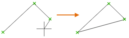
- Press Enter or Esc to end the command, or select the Close option from the command line to connect the last segment to the starting point of the first segment.
Click here for a detailed explanation of how to specify point locations and coordinates in AutoCAD.
B. Prompts and Options
When running the LINE command, several prompts and options may appear on the command line:
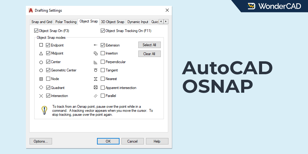
- Specify first point: Sets the starting point of the line. You can click directly on the drawing area or select a reference point from an existing object using the OSNAP feature for greater accuracy.
- Specify next point: Sets the endpoint of the current line segment. After specifying the endpoint, AutoCAD will prompt you to specify another point if you want to continue creating connected line segments.
For precise directions, use the ORTHO or Polar Tracking feature. - Close: Creates a line segment that connects the current endpoint to the starting point of the first line segment, forming a closed shape.
This option becomes available after at least two connected line segments have been create.
- Undo: Removes the most recently created line segment.
C. Example
The example below demonstrates how to create an object using the LINE command with several different point input methods.
We will create the object shown in the image below, starting from point A.
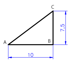
- Activate the LINE command
- Specify first point (A)
- Interactive Method: Click directly on the drawing area.
- Specify the next point (from A to B).
- Relative Cartesian Method: @10,0
- Relative Polar Method: @10<0
- Direct Distance Entry Method:
- Move the cursor to the right.
- Type 10 and press Enter.
- Make sure ORTHO mode is enabled.
- Specify the next point (from B to C).
- Relative Cartesian Method: @0,7.5
- Relative Polar Method: @7.5<90
- Direct Distance Entry Method:
- Move the cursor upward.
- Type 7.5 and press Enter.
- Make sure ORTHO mode is enabled.
- Specify the next point (from C to A).
- Using the Close Option: Select the Close option from the command line.
- Interactive Method:
- Click point A (Endpoint) directly.
- For accurate results, make sure the OSNAP feature is enabled.
Important: Pay attention to the use of periods (.) and commas (,) when entering coordinate values. Make sure they are entered correctly.
Leave a Reply