In this tutorial, you will learn about the function of the MIRROR command in AutoCAD and how to use it.
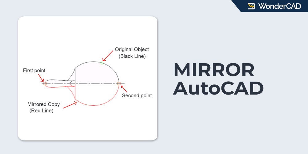
The MIRROR command allows you to create a mirrored copy of an object using an imaginary mirror line defined by two points in the drawing area.
This command allows you to draw only one half of a symmetrical object and then generate the other half by mirroring it, making the drafting process faster and more efficient.
The icon and shortcut for the MIRROR command are shown in the table below.
| Command | MIRROR |
| Function | Creates a mirrored copy of the selected object. |
| Icon | |
| Shortcut | MI |
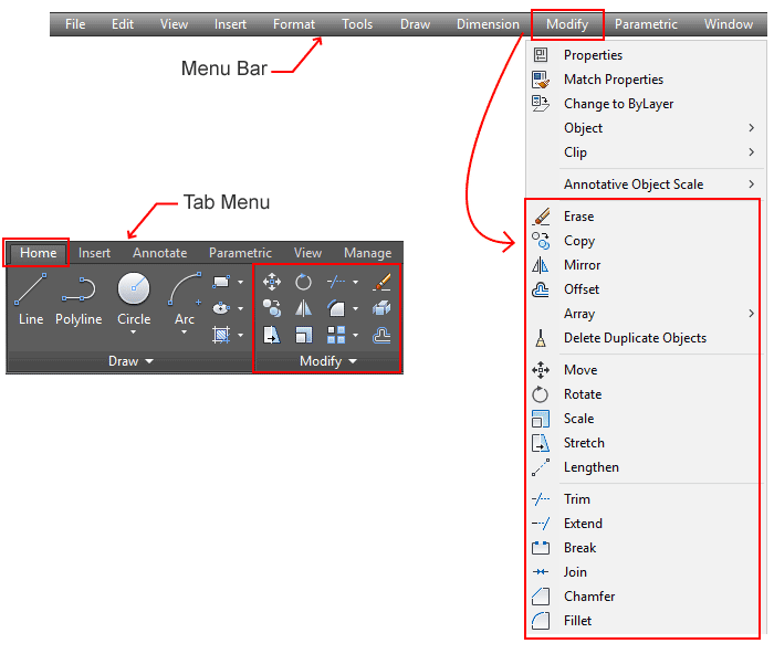
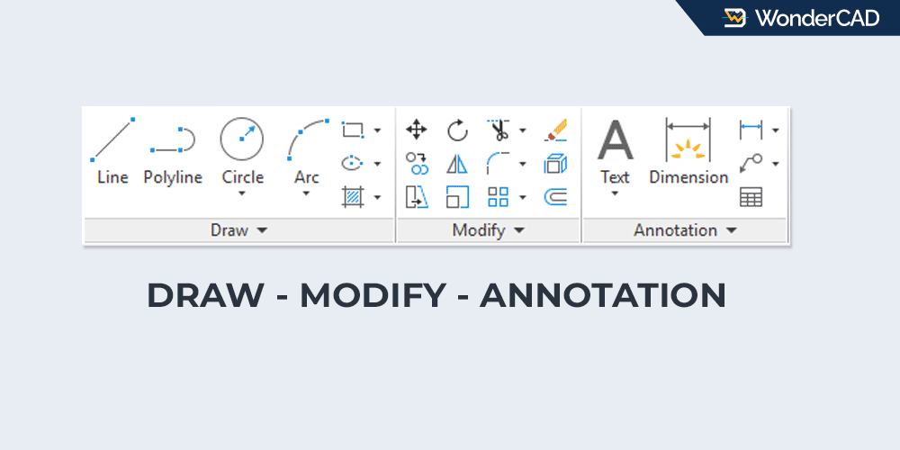
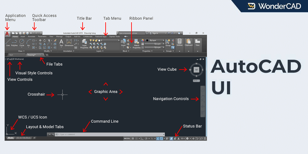
The MIRROR command is one of the most commonly used commands in the Modify group. You can activate it by clicking the MIRROR icon in the Modify panel on the Home tab of the Ribbon.
If your workspace displays the Menu Bar, you can also access the MIRROR command from the Modify menu.
If you prefer using the command line, simply type MI and press Enter to activate the MIRROR command.
When using the default MIRROR method, you will be prompted to specify two points. The straight line formed between the first and second points becomes the imaginary mirror line.
These points can be selected using references from existing geometry in the drawing area, or by clicking directly on the screen without any reference.
See the illustration below:
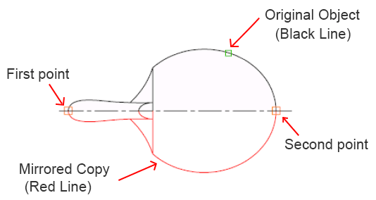
In the example above, the black objects located above the centerline are the original objects to be mirrored, while the red objects below the centerline are the mirrored copies. The first and second points are specified manually by the user. The imaginary straight line formed between these two points becomes the mirror line.
In this example, a centerline happens to be available, and its intersection with the main geometry is used as a reference for defining the mirror points. However, the centerline is not required. The MIRROR command can still be used even when no centerline is present, as long as the user specifies two points to define the mirror line.
The red color is used only to distinguish the mirrored object and make the example easier to understand. In actual practice, the MIRROR command does not change the color of the object.
If you define the mirror points using object references, as shown in the example above, make sure that OSNAP is enabled to ensure accurate point selection.
On the other hand, if you define the mirror line by clicking directly on the screen without using any references, it is recommended to enable ORTHO mode to keep the mirror line perfectly vertical or horizontal. Alternatively, you can use Polar Tracking to create a mirror line at a specific angle.
A. How to Use the MIRROR Command
To mirror an object using the default method, follow these steps:
- Start the MIRROR command.
- Select the object(s) to be mirrored, then press Enter.
- Specify the first point of the mirror line.
- Specify the second point of the mirror line.
- Erase source object? [Yes/No] <No>:
Press Enter to accept the default “No“ option. Alternatively, type “Y” and press Enter to delete the source object and keep only the mirrored copy.
Note: Most commands in the Modify group allow you to preselect objects before starting the command. Therefore, you can reverse Steps 1 and 2 if you prefer.
B. Prompts and Options
While using the MIRROR command, you may see some of the following prompts in the command line.
- Select Objects: Prompts you to select the object(s) to be mirrored.
- Specify first point of mirror line: Prompts you to specify the first point of the mirror line.
- Specify second point of mirror line: Prompts you to specify the second point of the mirror line.

Leave a Reply